


© all rights reserved G W Howe 2017 - 2020
Projects
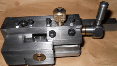
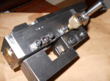
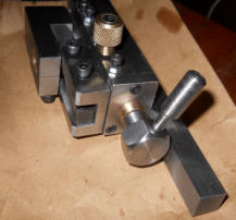
Project describing the making of a jig to turn small diameter bar on the lathe
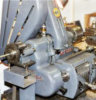
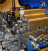
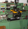
For many years I have wanted a reliable method for turning small diameters but have kept putting off designing or making one, Instead I have attempted to turn a small diameter a bit at a time which sort of works but is not ideal. Looking through some old editions of MEW I found what I thought might be the ideal solution, it was a design by Peter Rawlinson and it worked in a similar way to a conventional roller box jig. The design was good in that it allowed the cutter in-feed to be made in a controlled manner by having the cutter mounted in a block moving in a dovetail slide. The rollers, two small 16mm od ball bearings, were mounted vertically (one on top of the other) and this did worry me as to its ability to keep the bar being turned steady, however his article claimed it worked well for him and so I decided to base my version largely on his design. My requirements were for small diameters to be turned from 9mm od down and for the cutter setting be done off- lathe and the resultant turned diameter accurate to within 0.05mm. With these objectives in mind I set about making the jig according to Peter Rawlinson's drawings with a few minor dimensional changes (to suit the material I had in stock). The bearing roller part was exactly as drawn using new bearings purchased for this job but I did have some lingering concerns about how effective this design might be whilst making them. With the jig finished it was mounted in the lathe and some 5mm od mild steel bar used for the first test. The cutter feed was set to about 0.05mm to just clean up the stock bar and then I could run a second test to reduce the diameter to say 3mm od, or so I hoped. The lathe was running at a slow rpm for the size of material (600 rpm) but this should not have caused any performance problems and the bar stock was sticking out of the 3 jaw chuck by 100mm as I wanted to prove it would turn long lengths at a single setting. Immediately things went wrong with the stock bar lifting above the cutter tip which was fixed exactly on lathe centre height. The bar continued to lift and then started to move erratically to such an extent the only option was to stop the lathe. Needless to say the cutter made no progress reducing the diameter and after several more attempts the same problems reoccurred, something of a disappointment after the hours spent making the jig. Time to revisit the design and research how professional roller box designs work, plus look at other methods used to do this task. It seems most roller boxes place the rollers at 90 degrees when two rollers are used, exactly like a lathe follower support with each roller fitting in a slide having adjustment to position the roller to just touch the stock material. This approach was clearly better than the two rollers mounted just vertically as the top roller would be able to resist any tendency for the stock to lift however the back roller relied on the cutter to keep the back roller in contact. Another roller box design was to use three rollers but this was discounted as there was limited space to organise three adjustable rollers. Whilst these different roller design were clearly better it presented a few problems the most significant being that very small diameters would not be possible because the rollers would possibly each touch when using 16mm od rollers and prevent very small diameters being turned! Another popular method used by the ME fraternity was to dispense with rollers altogether and instead use a purpose made bush bored to the diameter of the stock so that it would easily slide on the bar yet constrain it in all directions. This design presented the simplest method and would cater for all diameters, even very small ones but did mean that a number of bushes needed to be made. Having spent some time making the original jig I did appreciate the overall design especially the cutter feed adjustment mechanism and so I decided to make a few simple modifications, the main one being the addition of the bush to keep it concentric. My modified jig was duly completed and set up for a test run to reduce 5mm silver steel stock down to 4.75mm, again having 100m length from the 3 jaw and running at 600rpm. The initial setting of the in-feed for the cutter was done off lathe and to help me judge the feed applied I had made the cutter feed- block nut and screw with 40tpi which is a convenient ME tap readily available. Using this thread a complete turn of the in-feed screw advance the cutter 0.025" or 0.64mm (approx.). Now I had fitted the screw end with a hex head so having 6 sides so it was easy to judge a turn of 1/12 (looking at the hex head it was either on the mid position of the hex flat or an adjacent corner). This, what might appear crude measurement scale, was actually surprisingly easy to use and accurate to 0.0025" or 0.05mm (approx) and clearly even finer divisions could be applied. When it comes to very accurate sizing especially with very small diameters of some length it often pays to apply some additional finishing method such as a very smooth file, emery or a hone, so for my purposes the jig with hex head method was good enough. Set up of the cutter is done off lathe and the cutter is fed in by turning the hex head until the cutter just touches the stock which protrudes out from the fixed bush (the cutter tip is positioned to follow with a very small gap behind the bush back face). The required feed is now calculated in terms of hex head rotation and with some degree of guessing for fine tuning locked in position using the top slide screw. The first test was a clean-up run removing a small amount of metal and the cut proceeded effortlessly with no sign of the stock bar moving out of centre. The resultant swarf did tend to fill up some of the 'air' spaces (later these 'air' spaces were enlarged) but this did not affect progress or performance. The finished bar was measured and found to be on size and consistent along the length. The next test was to remove more diameter using a new piece of 5mm silver steel bar to reduce it to 3mm od only this test was done having 'enlarged the areas where swarf might block) and once again the resultant tuned bar was on size and accurate within my expectations. Although the changes made to the Peter Rawlinson design were significant in that rollers had been abandoned and replaced with purpose made bushes the original design had many merits. It was a substantial jig with a cutter feed having a dovetail slide for rigidity and accurate setting and it performed consistently. The use of bushes is a minor inconvenience as these were made from 0.5" diameter stock (brass?) and drilled as needed, in fact ready-made bushes having a small diameter could be re-bored as needed. The time taken to make a bush was minutes and I consider it probably better to just make these for the job in hand rather than have a ready-made set of various bores because every new bush made would be first time use. Note the peg handle used to turn the hex head helpful should fingers be oily or to amplify the turn of the head when adjusting in- feed to small amounts.GWH Engineering
creative engineering in a home workshop