


© all rights reserved G W Howe 2017 - 2020
Projects
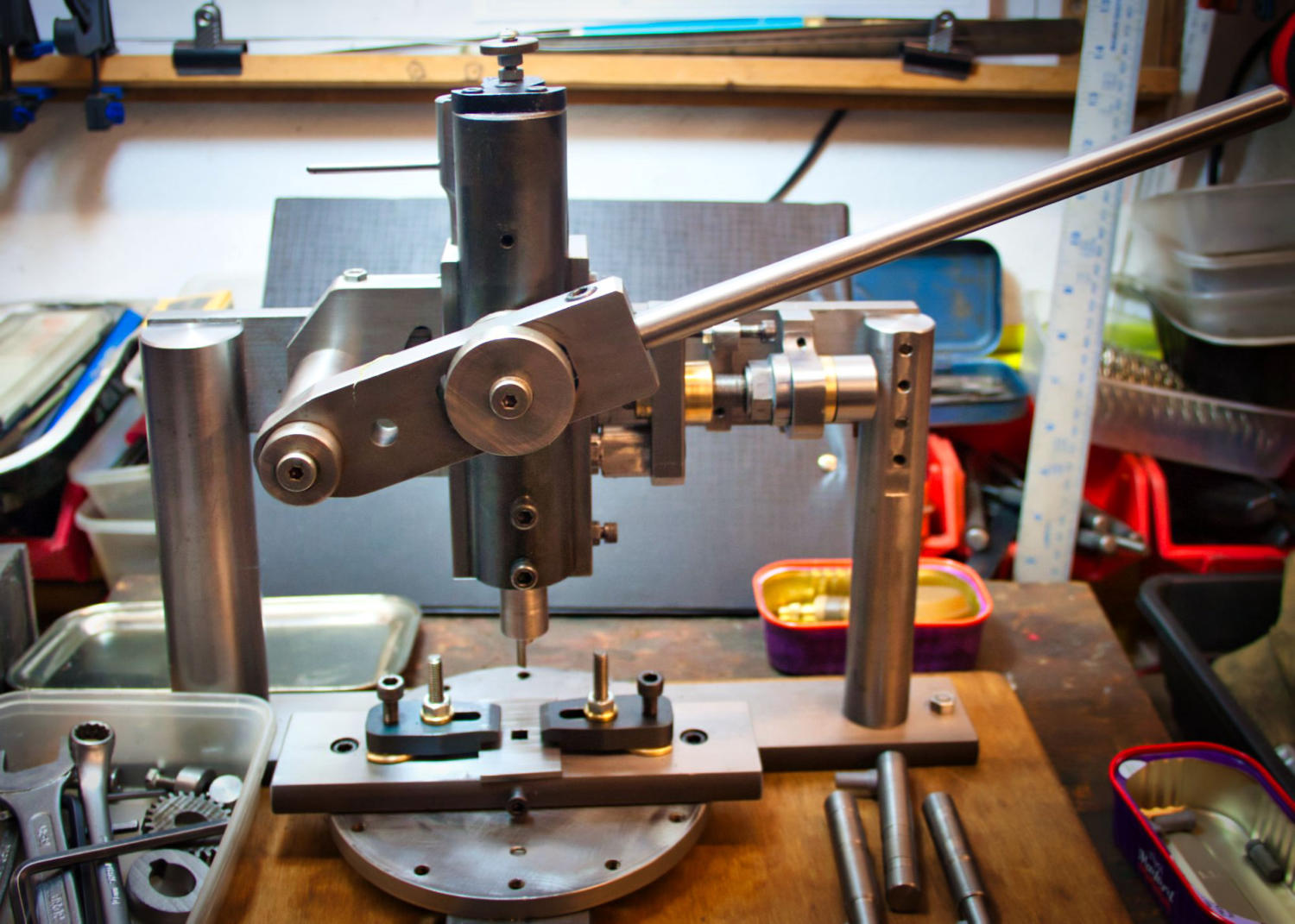
Project to make a bench Slotting (Keyway) Cutting Tool
I previously designed and made a slotting tool to mount on the lathe slide to enable keyways to be cut in gears held in the chuck. Whilst this approach worked I was always unhappy with the considerable forces experienced during the cutting process and this would be detrimental to the lathe and holding chuck. What I decided was to eliminate the need for the lathe and incorporate a cutter mechanism into a stand alone free standing bench jig. The main advantage was there was no possibility of damage to the lathe or chuck and a new design could incorporate new features, such as built-in centre alignment and multi radial cutting as in the case of a spline fitting. The new design has now been finished and used to slot keyways in gears and cut a square hole successfully. The jig is operated by a hand lever with the cutting forces concentrated into the vertical plane. The jig is free-standing on the work bench. There is a feed mechanism to advance the cutter horizontally which is adjusted by hand using a spanner. The spanner is long enough to easily judge the amount of feed in small increments which are shown as 12 graduated lines on the feed nut. Each graduated division equates to 0.003” feed however the feed can be adjusted to half this if required. Should the feed be too big then it can easily be reset and re- applied, the mechanism advances the cutter assembly along a dovetail. The whole central mechanism is supported by two substantial columns and a cross top member which has the dovetail built on to it. The base of the jig is a round table with a centre hole and 12 radial M6 holes tapped near the outer edge A rectangular 12mm thick steel clamp plate sits on top of the table having a centre boss so that it can rotate on the table. At either end of the plate is a M6 hole to match (exactly) the radially tapped holes in the table so that the plate can be positioned, or indexed. Note the use of a DRO is an advised help to ensure the holes exactly match. The top clamp plate has a 30mm centre hole into which fits a round 12mm thick disc with a bore appropriate to the bore of the gear to be cut and includes a clearance slot for the cutter. This approach enables a variety of different gear bore sizes to be slotted plus provides a simple method of placing the gear exactly on centre prior to clamping by using a bore setting pin (later removed before cutting). There are two clamps either side of the gear which clamp the gear using a ‘tool makers clamp’ approach. This ensures a very rigid clamping force and built into the end of each clamp has a small step recess and this prevents any tendency for the gear to move under the force of the cutting tool. All the major cutting forces are vertically aligned and do not affect the feed mechanism or clamps thus the whole jig remains very rigid and capable of withstanding wear or unwanted movements. The cutter, in the case of key way cutters, is cross-mounted in a short spindle which is loaded into the slotting ram. The cutter for square holes is end mounted. The radial alignment of the cutter is easily done by reference to the table centre line which is marked on the clamp mounting plate. Once aligned the feed will always move along this centreline thus ensuring a simple and accurate way to fix a gear to be slotted. Whilst the basic shape of the cutter is formed from round HSS it does need very careful grinding to ensure the width is as required. I use 3, 4, 5mm as my standard set each mounted and secured in a dedicated spindle. An advantage of this is to start with a small width cutter when a larger keyway width is needed. The change over is easy and quick and the cutting forces are much reduced when completing the final size. In the event multiple keyways are required the clamped gear on the mounting plate is simply rotated to the index position required. The clamps and gear remain fixed during indexing. The feed is reset and the cutting started from this new position. The jig can cater for various thickness of gears however to ensure the hand lever is at the optimum angle when applying maximum cutting thrust there is built in adjustment. The cutter and feed mechanism including the top cross rail can fit to two heights 15mm apart by the fixing to the end support column. A full set of drawings are available in pdf form, available on request.GWH Engineering
creative engineering in a home workshop