


© all rights reserved G W Howe 2017 - 2020
Projects
Project to design a belt drive fine feed mechanism on the BH600G lathe.
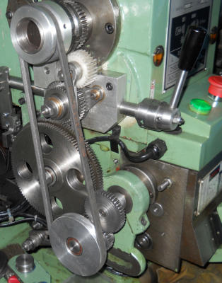
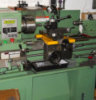
This project started some time ago following the making of a Screw Cutting Clutch unit designed by Gray Meek and based on that used on a Hardinge lathe. The BH600G lathe originally had a standard tumbler reversing arrangement to select forward and reverse feed or screw cutting direction. With the introduction of the screw cutting clutch the tumbler unit was removed as it already incorporated forward and reverse operation. Yet another version has now been implemented. The original design was basically very simple and easy to make in a couple of days So why change it? With time on my hands plus a desire to alter the design to provide feed in both directions. This has been nagging me for some time even though I rarely use feed towards the tailstock but when needed my original design failed this requirement. The original design follows on below but you can jump ahead to the new design article here. In its original configuration the BH600G lathe provided forward and reverse operation using the tumbler mechanism for both screw cutting and fine feed operation. In the case of fine feed operation, the gear train provided the power to the gearbox input gear. With the completion of the screw cutting clutch I decided that my next project would be to attempt to reduce the running noise which emanated from the gears in the gear train which is ever present as power feeding availability is always needed. Despite several efforts to reduce this noise using oils and even special open gear additives the noise was still unacceptable especially as the machine workshop is immediately below the main living room! This became a major issue as the screw cutting clutch had additional gears and this would slightly increase the noise but more importantly the gears and bearings in the clutch would wear quicker because the mechanism would be operational all the time due to the need for a fine feed drive. I had already thought along these lines when discussing the initial design requirements with Gray and asked that he incorporated a lever to easily disengage the clutch gears from the rest of the gear train. Of course with the lever disengaging the clutch it also disengaged the drive to the feed shaft and removed any fine feed! I prefer to accept a compromise solution when it comes to problem solving rather than build in complex designs which inevitably out-weigh the main user need. In my case the screw cutting clutch, which normally operates at slow speeds, provides the perfect solution for screw cutting needs and the resulting noise issues are minimal because the speed is low. This then left the need to design a solution to provide a quite drive for the fine feed especially as it operates all of the time and at faster spindle speeds. Initially this problem was solved by introducing a simple belt drive from the spindle direct to a pulley on the gearbox input shaft bypassing the gear train and this worked incredibly well, it was quiet and effective. but I was concerned it may cause wear on the gearbox input shaft bearing. The only other negative was the this new arrangement would provide fine feed in the forward only direction. This was not a major problem as most times I need forward direction and in the event I should have to use the reverse direction then this could still be accomplished by reverting back to the conventional gear train including the noise implications but for me, this is rarely needed. The direction issue could be sorted by introducing another tumbler mechanism into the mechanism but this would over complicate things considerably and also introduce more noise. In practice I rarely use reverse direction for feed but in the event it became essential then the screw cutting clutch can provide this even if somewhat noisily! The other remaining issue was the coarse feed rate which using the original set up with gears and tumbler mechanism gave ae bottom-end feed rate of 0.0047” and the new belt drive method provided an opportunity to resolve this issue. After some experimenting a final design evolved. The new arrangement is much the same as before with a belt being driven from a pulley fixed to the lathe spindle driving another pulley. Attached to the lower pulley spindle is a small 25t gear (20PA, 1.25MOD) which drives another 25t gear and this finally meshes to a 50t gear on the gearbox input shaft. The lower pulley and gear mechanism is fixed to a sliding arm which enables the gears to be quickly and precisely engaged to the 50t gear by way of an adjustable stop to restrict meshing movement . There are several advantages to this new mechanism: • it provides a much slower input to the gearbox shaft providing a range of fine feed rates, the slowest is 0.0017” compared to the original 0.0047” • noise level is very low • load on the gearbox input shaft is almost eliminated • the design is simple, elegant and easily engaged at correct mesh • quick and easy to remove giving full access to the main gear train A free set of drawings in A4 PDF format are available on requestRevised design (May 2020)
The original design was basically very simple and easy to make in a couple of days but whilst it worked without problems it did have some short comings. It could only provide feed towards the headstock; it was time consuming to change over to screw cutting as the fine feed unit needed to be removed; it required the gear door to be opened to make adjustments; there was no intermediate setting for no feed.Revised design (Jan 2023)
After some use I decided to revert to the basic original design as I never used the reverse direction feed and the spring tension device on the belt was not that desirable. The original forward feed design did not need any belt spring assisted tension other than done when setting the gear mesh. The selector plate remains with intermediate (no feed) and the reverse pin hole such that when reverse is selected it enables the belt to be easily removed. Change over to screw cutting is quick and easy and the fine feed unit can remain in place as there is now an intermediate setting for no feed and the change over to screw cutting can be done without having to completely remove the gear door. The latest revision was done using the parts made for the dual feed with minor changes. The drawings will be updated to reflect the change Operation of the unit is done without having to remove the end gear casing door and incorporates a similar lever handle in exactly the same way as the levers are used for the gearbox selection of speeds and feeds. The fine feed lever can be changed whilst the lathe spindle is turning though this is optimal when the spindle speed is not running at high speed. If needed the complete mechanism can be quickly removed ( 1 x M10 nut and 2 x M6 screws ) and replacement requires no special alignment process as there is only one gear in mesh and the lever operation determines the position and meshing of the gears. When it comes to wanting to set up screw cutting operations the fine feed driver 50t gear to the gearbox is removed (single M6 screw) and exchanged for the appropriate gear, commonly a 40t gear plus M6 fixing screw, which covers most screw cutting threads. The fine feed assemble remains in situation as it is clear of the main screw cutting gear train with the selector lever set to the mid position (no feed). Originally I planned for the index plate to be mounted on the gear cover door but in practice found this resulted in significant additional noise being amplified by the door being made from thin sheet steel in a box form. To get round this I added a new index plate which is attached to its own stand away from the door, which in turn is mounted to the lathe base tray. This tray as supplied is folded at the sides to improve rigidity and conveniently provides a base on which the new stand is fitted using a a steel square fitted under the folded ridge. This arrangement ensures the index plate is clear of the door and so no additional resonance is created and the door can be opened easily. The base plate of the stand is fixed with two M6 bolts to the top of the front fold with a sturdy square bar under and also has a third M6 bolt which provides a simple jacking method of adjusting the vertical alignment of the stand and index plate so that whilst close to the door it has about 1mm of clearance and the door can be opened unhindered by the stand. This fixing arrangement has proved to be very effective and the stand is completely rigid allowing the selector lever to latch as needed.GWH Engineering
creative engineering in a home workshop