


© all rights reserved G W Howe 2017 - 2020
Projects
Project to design a boring head with automatic surfacing.
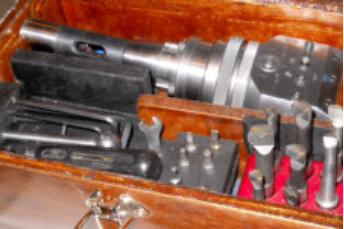
A quick look at the available commercially made boring heads revealed a variety of shapes and concepts all doing much the same job. Some are very sophisticated providing the ability to machine tapers or even screw threads. This is way out of my needs and what I wanted was a simple design that satisfied my three prime requirements so that the boring head could machine accurately with a fine feed and have an automatic facing facility.Design basics
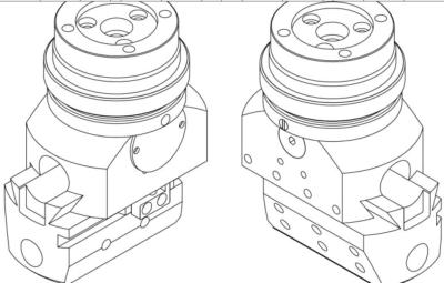
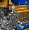
An essential need is for the head to fit various machines so incorporated into the design is the facility to attach different fittings such as an R8 shank. As an aside, I made the R8 shank from an existing R8 Morse 3 taper holder which was sitting in the tool cupboard waiting to be used. An attachment collar was made and permanently fixed to the outside diameter by way of high strength Loctite. The drive when used in automatic facing mode, must have a simple ‘clutch’ arrangement such as using two spring loaded balls to seat in a recess. The spring loading be adjustable and without having to dismantle the head. The drive mechanism uses a ‘star’ wheel with 8 teeth driven by two pegs for each revolution of the machine spindle. The star wheel is fixed to a shaft which has a worm thread mid-way and this worm drives a wheel. The decision to use a worm and wheel mechanism was initially problematic as I have not got necessary equipment to provide a geared down drive from the cutter to the wheel blank to keep the two in sync. As will described later this concern turned out to be overcome using a home-made cutter held in the lathe chuck and the wheel held in a spindle support attached to the the tool post. The final part of the drive is to move the tool block longitudinally within the dovetail slide way and this is done using a screw/nut arrangement with the nut being a thread cut into the wheel. The main body would be made from 3.5” diameter mild steel and the tool block from 2” diameter steel. To ensure the tool block could be set to ‘trip’ at a given diameter or at the end of of its permissible travel a ‘trip dog’ is used and this, when engaged, causes the the drive clutch to operate. The remaining design includes moving the cutter block quickly or ability to make fine manual adjustments when reaching finish diameter.Making
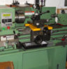
Making the main body is relatively straight forward however the cross hole for the worm spindle needs to be accurately positioned as per the drawings. The sides are rough milled slightly over-sized and then set up in the lathe 4 jaw chuck to bore the long 0.7” dia. hole. It is important that this hole is parallel and centred so setting up in the chuck was carefully done. Drills have a habit of wandering on deep holes so drilling was done a bit at a time ensuring that the lead drill (smallest) had plenty of clearance by follow up larger drills. This method is slow but the hole finished up exactly where it should so worth the effort. The dovetail was now milled so as to give access to fitting the worm/wheel. Next making the worm and wheel. The worm was relatively simple but a slow screw cutting task being 10tpi and at the same time making another replica thread which would be used later to make the wheel cutter. The wheel cutter was made from mild steel and case hardened. Five grooves were milled along the length and the teeth then backed off by hand with a file. The actual wheel was made from phos.-bronze bar and turned to od size plus a central hole drilled and tapped 5/16” BSF (22tpi). The wheel was then screwed onto a stud previously threaded to match and then fitted to a simple jig such that it could be mounted in the lathe tool post. The wheel cutter was mounted in the 3 jaw chuck and gradually brought into contact with the wheel blank. No guide teeth had been cut as I was unsure how this process would work but the cutter duly rotated the wheel blank whilst forming the teeth. All this was done using a slow back-gear speed so easily controlled. The teeth formed (21) were as good as I might have hoped for and the total task time was a few minutes. I decided to now fit the wheel and worm to check the two would mesh correctly. The long 0.7” hole allowed for a small amount of positioning so that the mesh was correct. This positioning utilised two mild steel rings fitted to the wheel at either end. The rings had a bottom hole to locate to a peg in the main body and two side holes to ensure position. The main body was then drilled and tapped for these side positioning screws. The rings needed to be drilled to locate to the ends of the screws and using the screws in a light assembly the screw ends would mark the ring so that the holes would align. This method ensured the wheel was firmly located in the main body and could be easily aligned when the feed screw was fitted. The worm was now completed including a star wheel which would index the worm, a socket head screw loctited at the dial end and a peg to key the star wheel. Also made, the index marks for the dial (should have been done later for precise alignment!). A simple cover end-plate to press up against the end of the worm and a small retaining pin used to keep the worm captive. Next job is to make the drive mechanism and ‘clutch’. This is a simple turning job and comprises a ring with a recessed groove on the underside into which are fitted two pegs diametrically opposed. These pegs as they pass the ‘star’ wheel cause it to index the worm. It is important the pegs are shaped so that they index the star wheel teeth correctly and ensure the following peg does not bind. On the top surface of the ring are two round recessed shallow holes which later have inserts fitted. The inserts are made from silver steel with a brass centre and are drilled to form a dimple recess for a ball to locate. The ‘clutch’ arrangement is a safety aspect such that when the head is used in automatic facing mode if there is a cutter bind or the end of the allowable feed is reached the clutch will give way. The clutch is another ring to sit on top of the peg-ring and has two holes tapped to align to the ball inserts. Into these tapped holes screws a small plug which contains a spring and ball such that additional pressure can be applied to the ball by screwing downwards. Finally a set of two top rings are made, one to keep the drive rings captive and able to rotate smoothly and the other to enable a shank to be subsequently fitted. The two upper rings both bolt down into the main body to ensure rigidity, including an M8 bolt and 4 x M5 bolts. With the shank unconnected it is possible, using a thin screw driver to adjust the spring pressure on the balls without having to dismantle all the parts. The remaining major part is the tool block. This is made from 2” round bar however this is a bit tight and so 2.5” bar may be safer. Complete the dovetails so that the part will fit to the main body (only) using a gib strip. With the two parts firmly fastened together the tool block can be turned to match on diameter and the three 0.5” tool holes drilled, bored and reamed. Done this way the centre hole is guaranteed to be concentric and the other two holes spaced apart equally (0.875”). The longitudinal 0.5” tool hole is drilled as before in the 4 jaw chuck and even more care must be taken to ensure the drill does not wander from end to end. The stop-dog slot was originally going to be another long smaller hole but the chances of this going wrong made me change design and instead mill a square slot and then follow up by milling with a 1/8” dia. end mill angled sides to form a sort of dovetail effect. This method has proven to be ideal and easy to make. In order for the tool block to fit with the worm/wheel mechanism it requires a further part hole recessed on the top. I did this in the lathe using a boring bar with the tool block fastened to the lathe cross slide. This recess needs only to allow clearance and whilst it looks better to be a perfect match to the main body hole any small errors are not important. Before milling the angled sides of the tool block the clamping holes (8) should be drilled and tapped M5. Finally, the tool block requires two recessed places either end for the feed screw to be fastened. The end pieces that fit to the recesses need to be aligned such that there is no binding along the full length of travel and one has a small amount of adjustment using slotted holes.Specification:
Cutter feed can be applied using drive ring (manual & auto facing), dial adjust or tool block quick set) manual using drive ring - per rev of ring 0.0005” auto facing - per 100 rpm of drive* 0.050”/min. dial adjust - per rev. of dial 0.002” quick set (tool block end) - per rev. of screw 0.045” tool block 3 vertical, 1 end 0.500” dia. tool shanks spacing of vertical tool 0.875” centres tool travel to trip (max) 0.880” * drive speed depends on material being cut (sfm), tool material and largest diameter being faced. [ rpm = sfm * 12/ pi * dia.] Drawings available on requestGWH Engineering
creative engineering in a home workshop