

© All rights reserved G W Howe 2017

Gear making site
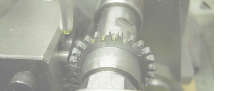
the Gear Generating Machine
specification
Gear Blank Diameter min. 0.625” dia. max. 8” dia. Gear Blank Bore Diameter Large arbor min. 0.5” dia. max. 1.0” Small arbor min 0.25”dia. max. 0.5” Gear Thickness max. 0.625” Number of Teeth in Gear Dependent on method/gear set configuration Teeth cut per cycle 1 or more, dependent on DP Cutter Stroke 1" Cutter Thickness/Teeth 0.25” thick, 4-5 teeth DP Range 20 - 48 Arbor Rotation rack & gear method Gear Profile Generated involute Generation Method Sunderland Cutter Strokes per min circ. 40-50 Castings used none Framework steel plate (0.5” or 12mm thick) Operation fully automatic after setting for first gear tooth Bearings ball bearing and phosphor bronze Drive Reduction motor – belt then compound gear train (basic high ratio) Cutter Lubrication mech. recirculated pumped systemScope:
Number of Teeth The number of teeth that can be machined is only dependent upon the method used to rotate the gear blank fixed to the arbor. All methods make use of a rack and gear(s) in mesh. The gears can be single or configured as a simple or compound train. Some gear teeth numbers will not possible unless a direct copy of the gear is available. For convenience, a set of gears has been selected to form a standard set and this set will provide a large range of numbers dependent on the configuration devised. The standard gear set comprises: 20, 25, 30, 35, 38, 40, 45, 50, 55, 60, 65, and 70 teeth gears, all of DP20 and these actually came from a Myford ML7 lathe (14.5PA, DP20) Methods The numbers shown below are by way of example and make use of the standard gear set. Direct Gear Rotation Method - uses the standard gear set where the DP is the same as the standard set (DP20). 20, 25, 30, 35, 38, 40, 45, 50, 55, 60, 65, 70 (‘n’ teeth) Indirect Gear Rotation Method - uses the standard gear set configured as a gear train to provide teeth numbers different from those in the standard set but the DP is the same as the standard set (DP20). For example, in the range 18-57 the following are possible: 18, 19, 21, 22, 24, 26, 27, 28, 32, 33, 36, 38, 39, 42, 44, 48, 49, 52, 54, 56, 57 Gears not possible - 23, 29, 31, 34, 37, 41, 43, 46, 47, 51, 53 Different Gear DP/Mod Method - This method incorporates both the direct and indirect rotation methods above and uses the standard gear set but significantly, enables the generation of gears having a different DP or Mod to that of the standard set. using the standard lever attachment - DP 24, 30, 34, 40, 48 - MOD 1.0, 0.9, 0.8, 0.7, 0.6, 0.5 note: additional lever attachments can be easily made to cater for other requirements as long as DP required is > standard set (DP20) Direct Copy Rotation Method - A direct copy of a gear can be made for any gear having DP or Module notation, within the size limitations of the machine. This method requires a corresponding cutter rack and a rotation rack which meshes to the gear being copied.