
© All rights reserved G W Howe 2017

Gear making site
the Gear Generating Machine
operational design considerations
As previously mentioned the involute profiling machine uses a totally different mechanism to enable the arbor, with gear blank fixed to it, to rotate. This aspect of the design was initially a problem when trying to think of an alternative to the that used in the conventional Sunderland machine since it had to be relatively simple in concept yet provide the same function. The rotation of the arbor is crucial to the success of generating an accurate involute curve because the rack cutter reciprocates across the face of the gear blank it then also moves vertically and whilst this is taking place the arbor must also rotate in direct synchronisation to the amount of vertical movement.rack solution to rotation of the arbor
The main operating principle of the Sunderland machine is that a rack can mesh perfectly with any gear of the same specification and cause rotation. With the Sunderland the rack is used as a cutter but it is still adhering to the concept of being in mesh with a gear, in this case the gear blank however, as the rack gradually planes or cuts out metal in the space between the gear teeth to be a special mechanism, probably a worm wheel arrangement, rotates the gear blank on the arbor. This process generates an involute profile. In the case of the smaller prototype machine this solution was only partially used. Because it would have been difficult and complex to emulate the Sunderland rotation mechanism I decided to make use of another rack meshed to a gear. Now if this other rack, renamed the rotation rack, moves vertically at exactly the same rate as the cutter rack then if anther gear is attached to the arbor with which the rotation rack can mesh it must obey the principles required to generate the same exact involute profile. This for me became the realisation that a prototype machine was both feasible and practicable.method of rotation to increase scope
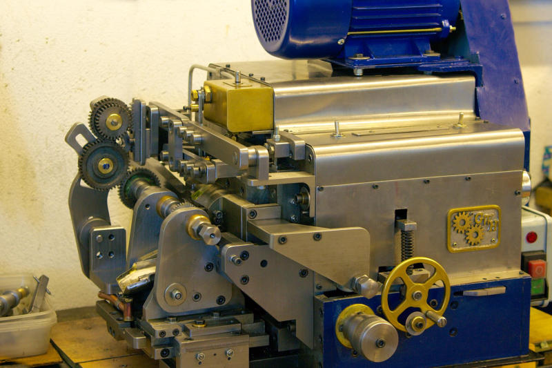
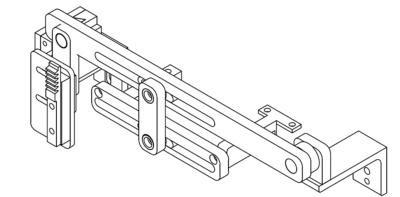
The basic method was simple and elegant but relied on the need for the rotation gear to be the same specification and size as the gear being made, in or words this was a simple copy method. As such, the copy method was very restrictive as it always assumed a gear and rack to match the gear being made were already available and in most cases that was unlikely. The next method was a simple adaptation of the copy method but now included a gear train between the rotation rack and arbor gear. This method now enabled gears of the same specification to be machined but now could have a different number of teeth. For example, a gear to be made is 28 teeth but using a suitable gear train this can be done using other gears where none of them are 28 teeth size. This approach then suggested the rotation gear and train could comprise a standard set and to this end I used spare gears from my Myford ML7 for this purpose. The last method adopted was to exploit both the first and second methods but in this case make gears having a different specification, PA and DP, from that in the standard rotation set. The standard rotation set was derived from a Myford and these were all 20DP and 14.5PA. What was now needed was a method by which the machine could, using this standard set, make gears having a different DP and PA, for example DP32 and 20PA. The solution was along time coming but eventually it dawned on me that the key to this was the relative circular pitch (CP) of the gears. The cutter rack in all methods moves vertically a distance which is in total, for a tooth, equal to the CP or whole multiple thereof, so for example machining a 28DP gear the cutter rack would move vertically 0.1122”. The standard rotation set however is 20DP and this is has a CP of 0.1571”. If some mechanism could be devised such that the rotation rack was adjusted so that rather than moving vertically 0.1122” (since it is tied to the cutter rack movement) it moved 0.1571” for the rotation rack then the rotation of the arbor would be in direct synchronisation. Sounds complicated but in practice the solution followed by using a lever and two links which gave the correct adjustment. sketch shows the attachment described in the last method installed on the Gear Generating Machine, note the design has changed from that in the machine photo, below, to incorporate a sliding adjustment instead of fixed position buttons.